Instruments, Technology
RCA Theremin Service Notes
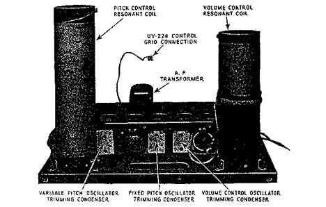
Referring to the schematic circuit Figure 4 and 5 and starting from the pitch control rod we find the circuits functioning as follow:
The pitch control rod is connected to a coil having a very high inductance. Connected to this coil is a small condenser and a small concentrated coil. This entire circuit is tuned by the distributed capacity of its coils and resonates at approximately 172 K.C. Not having any fixed capacitor connected across it for tuning, the ratio of inductance to capacitance is very high. Thus the small increase of capacity caused by the hand close to the pitch rod will cause the circuit to change its natural period considerably, a great deal more than if a large capacity and small inductance were used.
This pitch control circuit is connected to the grid side of the variable pitch control oscillator the frequency of which is slightly greater than that of the pitch control circuit. Bringing the hand close to the pitch rod will increase the parallel capacity in that circuit and thus reduce its frequency. As this capacity is reflected in the oscillator circuit a similar decrease in frequency will result in that circuit, the amount of decrease depending on the closeness of the frequency of the two circuits. Thus a greater decrease in frequency of the oscillator circuit is obtained when the pitch control circuit is close to the oscillator circuit in frequency than when it is at a greater frequency difference.
The next circuit to examine is the fixed pitch oscillator. This circuit oscillates at a frequency, when correctly adjusted, at a maximum of 1400 cycles greater than the variable pitch oscillator. The amount of this difference is dependent on the frequency of the variable pitch oscillator the frequency of which is determined by the position of the hand in relation to the pitch control rod. The frequency of the fixed pitch oscillator does not change’ while playing.
An example of the functioning of these three circuits follows:
The hand approaches the pitch control rod and increases the capacity across the pitch control circuit. This capacity is reflected across the variable pitch control oscillator and thus reduces its frequency. This causes an audible frequency difference between this oscillator and the fixed pitch oscillator, the frequency of this note depending on the position of the hand. Bringing the hand close to the rod will increase the capacity in the pitch control circuit, reduce the frequency of the variable pitch oscillator and increase the difference between the frequency of this oscillator and the fixed pitch oscillator. Thus an audible note is obtained, the note increasing in frequency as the hand approaches the pitch control rod.
Examining the circuit diagram we find that each oscillator grid is connected to the control and screen grid respectively of a Radiotron UY-224. As the screen grid has the largest area, a 10,000-ohm resistance is connected in series with it to balance the input to this tube and have each oscillator have the same effect on the detector action. This tube is a detector or combining tube that functions much in the same manner as the first detector in a super-heterodyne circuit.


