Technology
Of the Theremin Making
Giorgio Necordi’s short report about the making of his transistor theremin.
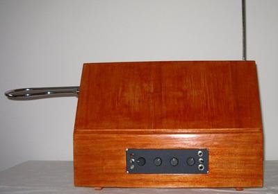
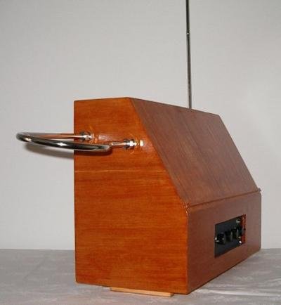
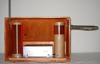
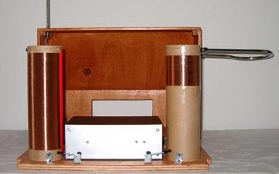
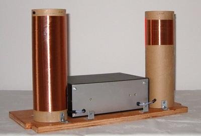
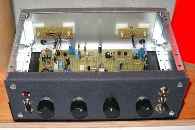
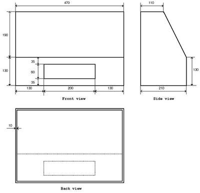
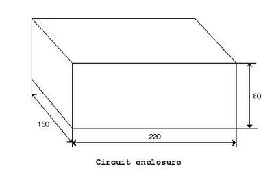
After a long wait it’s time to come out and unveil the instrument based on my long time experiments with theremins. This is the theremin you can hear in the “theremin samples” section of the thereminvox.com library The entire instrument was completed during 2003 and revised many times during 2004 and 2005. What follows is a collection of specifications, images and mechanical details of the instruments.
| Instrument specifications | |
| Musical range: | 5 1/2 octaves – 3 octaves above middle C |
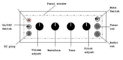
| Controls: | Pitch tuning, volume tuning,waveform, high tones cutoff, mute switch, power switch, power on led |
| Outputs | Audio, tuner/pitch preview |
| Power supply: | External – 11.50 Volt |
| Volume antenna: | standard loop antenna |
| Pitch antenna: | telescope rod antenna partially opened |
| Playing arc linearity enhancer: | Big air coil |
| Pitch oscillators frequency work: | 210 KHz |
| Volume oscillator frequency work: | 440 KHz |





Would love to buy one. do you have any for sale? DS
I would also
Hi,
I would be interested to have a copy of the circuit diagram (and coil specs) that you used. Any chance you could add them to the story?
Hi,
>
> I would be interested to have a copy of the circuit diagram
> (and coil specs) that you used. Any chance you could add
> them to the story?
> >
> > Hi,
> >
> > I would be interested to have a copy of the circuit
> diagram
> > (and coil specs) that you used. Any chance you could
> add
> > them to the story?
>
I would be interested to have a copy of the circuit diagram (and coil specs) that you used.
>
> I would be interested to have a copy of the circuit diagram
> (and coil specs) that you used.
Hi,
it’s possible to have the schematics of the project?
Thx very much!
> Je serais intéressé d’avoir une copie du schéma de circuit
> (et des spécifications de la bobine) que vous avez utilisé.